Repairing a dK'Tronics Keyboard and Scoping Out a ZX Spectrum 48k - Part One
Sunday, 17th March 2013, 23:51
A few weeks ago I managed to get a cheap dK'Tronics keyboard from eBay, which was like most of the old retro kit I get off there, cheap because it was not exactly 100% working and needed a bit of repair work. But that is how I justify these old purchases to myself, if I don't pay very much and I restore it to former (or close to former) glory, then I've been entertained for a few hours (or days depending on the project) at a very low cost.
Repairing the Keyboard
People may remember the old classic rubber key ZX Spectrum with fondness, I know I do. Though as a child I was seduced by adverts on magazines about a "proper" replacement from a certain company. The idea was you payed £15, which is around £44 in today's money, and got a large plastic box with real keys on it, that you opened up and inserted the motherboard of your Speccy.
I could never afford one, I'd have had to save for weeks and would only have gone and spent the money on games anyway. I'm a bit older now, and earn a little more than when I did a paper round, so I can afford the £12.94 (plus £9 postage) for what is now quite a rare item and included a Spectrum inside to boot.
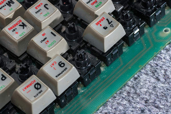
Opening it up, things inside are very simple and spacious, the keyboard is mounted on a circuit board that screws to the top part of the housing, whilst the Spectrum motherboard screws to the lower half. The cables that connect the two are far more sturdy than the cheap plastic painted equivalents that Sinclair used, the ones that crack over time and if removed and inserted too often.
The keys themselves work the same way as remote controls, conductive rubber, with a resistance of between 50-200 ohms, shorts two points to complete the circuit. Dismantling them whilst they are soldered on the board is a nightmare, and I broke a few trying until I gave up and decided the better route would be to desolder them.
Thankfully desoldering the keys from the board is ridiculously easy, I've had problems with old kit sometimes in the past even getting the solder to melt properly, no trouble here, they practically fall off! The downside is some of annular rings, the little metal points around the holes where components go through that the solder grips to, can just drop off. I guess over the years whatever bonds the metal layer to the board, degrades.
So after removing and dismantling buttons, fixing and replacing them, I had to get the meter out and fix any connections which were now broken. Annoying but trivial, hazards of desoldering old equipment alas.
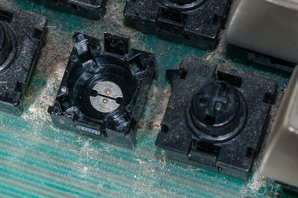
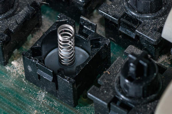
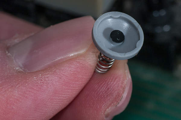
The buttons themselves are quite simple, you can just insert a flat bladed screwdriver or those little soldering aid sets Maplin sell have a useful blade which I prefer. Once opened and making sure you didn't lose the spring, cleaning both the rubber and the metal contacts with alcohol, I use Meths, is all you need really.
You can work out what buttons are gone by putting a meter across them and pressing. Once cleaned you can tell if they need a bit more of a clean by again measuring the resistance and try to get them under 100 ohms if you can, above that and you'll find they begin to become less responsive.
Whilst It's Open, Let's Scope It Out!
If you just look at a Spectrum motherboard when the power is on, unless it is smoking, which is not a good sign if you were wondering, then seeing what is going on is hard. One useful thing you can do is check parts of it with a multimeter. You can for example check the power socket and make sure the 9V supply is delivering enough voltage, and that the voltage regulator is working.
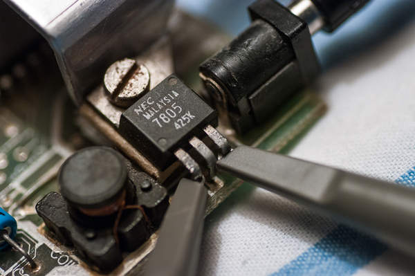
But that doesn't show you the whole picture. Stick an oscilloscope on the above and you can see a much more detailed picture.
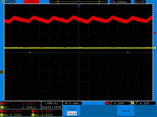
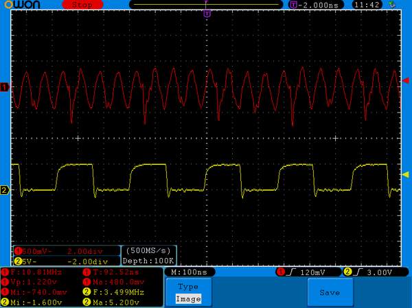
In the above image, each square of the grid represents 2 volts, the red line is the incoming voltage from the power supply brick, and the yellow line is the output of the voltage regulator. The scope shows that rather than delivering 9 volts, the genuine Sinclair PSU is actually delivering between 9.8v and 11.68v. So it's clearly a cheap unregulated brick and also very noisy and oscillating at that.
On the other side of the 5v voltage regulator is a much more consistent and cleaner signal, but you can see that to achieve this it has to convert a few volts to heat which explains why the thing has such a huge heatsink attached to it.
The Clock Speed
Computers are a digital system, and whilst many things inside them are happening at the same time, everything has to work off a single timebase otherwise things get out of sync. Everything in a Spectrum is run off a 14Mhz crystal oscillator, which is the fastest rate anything inside it happens at. You may already know that the CPU inside runs at around 3.5Mhz, which is a quarter of the speed of the oscillator.
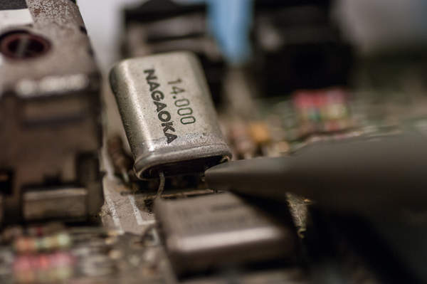
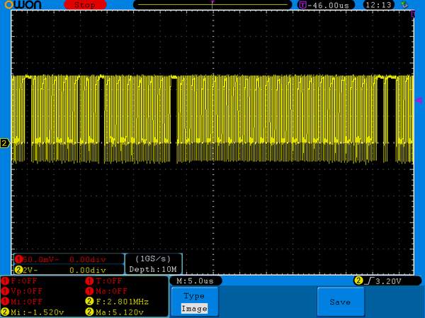
Let's put the scope on the output of the crystal and see what actually comes out of it.

I'm not sure you would call this a sign wave, I should really have set it to present an average to see what it looks like minus the noise, maybe next week I'll do that. Anyway, the frequency is around 13.86Mhz, which in new money is 72.13 nano seconds between each peak. Not exactly 14Mhz but it's clearly close enough most of the time for what the various chips inside desire.
Note that the output of the crystal is an AC wave, this is clearly an analogue signal and useless for driving a chips. At some point it will have to be converted into a digital trigger signal.
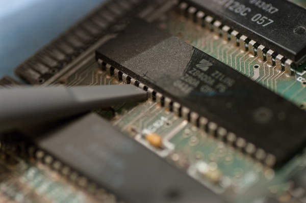
Next up I've added the CLK input pin of the Z80 chip, this is a very important pin, if no signal is sent to this pin then the chip will do nothing.
The yellow CLK trace is now clearly digital in nature. The red and yellow numbers on the left of waveforms represent the zero point. I probably should have mentioned that earlier, if you go back to the PSU voltage image earlier, you can't see the 1 because it's hiding behind the 2, they are at the same level.
You can clearly see here that every fourth peak of the crystal output correlates to one peak of the square wave which drives the Z80 CLK signal. They aren't perfectly square, the rising edge is slighly curved and the trailing edge actually drops to a negative voltage, but it's good enough for a Z80 chip to follow.
Everytime the chip gets one of these rising signals, it performs an internal clock tick. Some instructions take a few ticks to execute, this is because it can take one tick to set the state of internal registers, and additional ticks to operate on them.
If we look at the same trace closer, you can see how noisey reality is in comparison to those dead square diagrams you often see in books.

All CPUs have a maximum clock speed above which they will often either do one of a few things, behave eratically, overheat or just ignore any clock signals arriving at a pace it can't handle. The Z80A is rated at 4Mhz, so Sinclair went with a conservative 3.5Mhz, presumably because it is a lot easier to divide the crystal freqeuncy by 4 than a fraction.
A CPU Clock WTF
Watch the CLK signal for a short time and you'll soon see something strange, it's occasionally missing.
There are two questions worth immediately asking about these occasional irregular missing clock signals, should they be there, and why do they not cause the Z80 CPU to crash?
Handling the second question first, CPUs have internal registers, if they aren't fed a constant tick then their contents can die. The Z80 however is different, in fact it is apparently the only significant CPU ever made that doesn't need this.
You can actually pause a Z80 CPU, indefinitely, by stopping the clock signal for as long as you want. Maybe an interesting project down the road would be to add an adjustable divider to the clock signal so you could slow the CPU down to a halt if required. Not that anybody has ever said they thought the Specrum runs too fast. :)
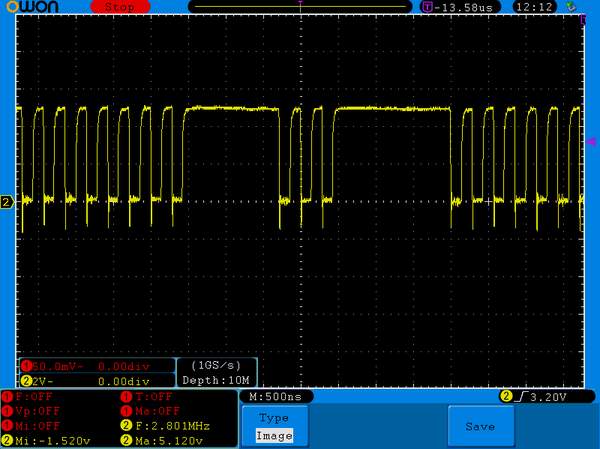
Now back to our first question, why are there gaps in the clock signal at all? Well, the answer is simple, memory contention. The Spectrum has an amazing multi-purpose chip called the ULA, aka the Uncommitted Logic Array. This is what makes the Spectrum a Spectrum, it handles everything from the sound output and tape input, to generating the video display and reading the keyboard.
When it generates the video output, something it has to do 50 times a second, it needs to read bytes from the block of RAM allocated to the display. If the CPU needs to read or write to the same area of memory at the same time, there comes a problem.
This collision would result in one or the other failing, neither of which is desirable. You don't want display corruption, that would mean garbage randomly appearing in parts of the display, and you certainly don't want your program thinking it's succesfully written or read from memory when it hasn't.
How the designers solved this little problem is declaring the 16k bank of memory where the display sits as contended memory. Now since the ULA creates the clock signal for the CPU, whenever the CPU tries to read or write to contended memory whilst the ULA is doing the same, it can do something quite simple, just stop sending clock signals until it's finished.
This is exactly what happens, and you can see above that the results are unpredictable so if you really need to maximise the CPU speed and take advantage of every clock you really need to make sure you never read or write to that block of memory (including accessing CPU instructions, so code shouldn't be in that bank either) when the ULA is updating the display.
In the next part, I'll show you what the video display output looks like.
Comments
posted by Robee on Tuesday, 22nd March 2016, 22:49
Wow you really are a keyboard nut! :)
I would describe the DK'Tronics keyboard as, er, not very nice. Nothing like a nice cherry keyboard in feel.
posted by Ahmad on Monday, 9th May 2016, 17:39
Thanks for letting me know! I have this ongoing debate with a friend that all though the BBC Micro (ya, boo, hiss!) had a mechanical keyboard that was superior to what was out there back then, it was quite a heavy and sticky touch compared to modern mechanicals; short on (key) travel too.
posted by Robee on Monday, 9th May 2016, 17:52
Aw the BBC Micro has a warm place in my heart, I played Elite and did a lot of BASIC on it, although the only machine code I did was Z80.
Looking back, yes the keyboard isn't a patch on modern ones.
One day I may find myself having to learn a bit of ARM assembler, but it's almost as if C and computer speeds has spoiled things a lot, you hardly ever *have* to get dirty.
posted by Ahmad on Tuesday, 31st May 2016, 14:11
Small world! You’ve mentioned ARM Assembler to someone who teaches it! During occasional chats with others (undergrads and staff) I tell them that most of my knowledge of assembler comes from learning Z80 assembler on a Sinclair Spectrum (many don’t know what one is! degree students are a bit young for that). The root concepts are the same, it just feels as if all those limitations you had with a Z80 have just been removed, e.g. registers are all general purpose (and 64 bit!), you can use them for data and addressing etc.
The BBC Micro was excellent, great Mode 2 colour graphics, very good Basic, in-line assembler etc. but at £400, only one (well off) kid at school had one, nearly everyone had a C64 or Spectrum though.
posted by Ahmad on Tuesday, 22nd March 2016, 22:43
Thank you for a truly fascinating article, I teach ARM assembler these day, but cut my teeth on a Spectrum. I also had a DK'Tronics keyboard, I am curious as to what the key switches 'feel' like, when compared to modern Cherry Switches, I'm a bit of keyboard nut myself...
http://furbian.blogspot.co.uk/2014/12/keyboards-keyboards-keyboards-and-yet.html
With regards to the concept of 'contended' memory, seems like the concept of the Commodore Amiga's 'chip' memory had a predecessor.